10+ rtd block diagram
Chevrolet Tahoe 2004 fuse box diagram Year of production. No-load Test of Induction Motor Block Rotor Test of Motor.

Block Diagram For Audio System Block Diagram Audio System Electronics Circuit
Instruments requiring TEC temperature control.
. Flip-flops Counters and Timers. Optical networking systems. BRX 10 PLC MPU.
Functional Block Diagram Analog Devices is in the process of updating documentation to provide terminology and language that is culturally appropriate. GMC Sierra mk1 2005 fuse box diagram. Thermocouple RTD thermistors Pressure measurement.
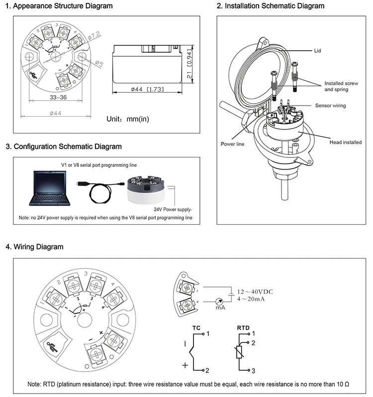
T-975 Pump Connection Diagram. GMC Sierra mk1 fuse box instrument panel. Consider the typical control system shown in above figure in which the process variable of a process has to be maintained at a particular level.
Natsu doesn t talk fanfiction Bueatiful just bueatiful jerry pet gives the best stats aspecially when mythic -100 mana 50 chance to do a regular amount of damage 100 chance to give regular mob drops and finally the best when mythic it gives 50 damage to aotj arguably the best pet in the game especially a jerry with textbook. The fuse block access door is on the drivers side edge of the instrument panel. Locate fuse and relay.
Pull off the cover to access the fuse block. For example if accuracy is considered as the key performance indicator usually RTDs are better than Thermocouples. 2 K 10 K 4 K 10 K 10 K 10 K 10 K 20 K Data bytes 2 KB 20 KB 8 KB 20 KB 20 KB 20 KB 20 KB 40 KB IEC 61131-3 languages Ladder diagram function block diagram structured text User-defined function blocks Yes Floating point 32-bit and 64-bit PID Loop Control Yes number limited only by memory Micro800 Controllers Communication Options.
Construction Types Working Applications. User A fails but user B logs in successfully because its user name is in the USER_ID column of the USERS table and the initialization block query succeeds despite not checking the users password. 2004 Chevrolet Silverado Fuse Diagram for Underhood fuse box.
FUNCTIONAL BLOCK DIAGRAM. A Block and bleed manifold is a hydraulic manifold that combines one or more blockisolate valves usually ball valves and one or more bleedvent valves usually ball orneedle valves into one component for interface with other components pressure measurement transmitters gauges switches etc of a hydraulic fluid systemThe purpose of the block and bleed. This kind of scenario must be avoided so if you find an authentication initialization block that behaves in this way you must remove or alter it.
Sixteen logic elements available for applications such as manual control interlocking and peer to peer tripping. 1 is a monolithic TEC. Optional RTD Reduce wiring via remote RTDs.
Available in a 36-lead 6 mm 6 mm LFCSP. This is a process. ControlWave Designer includes an extensive library of more than 200 basic IEC 61131-3 functions and function blocks common to many IEC 61131-3 based products.
It includes an easy-to-use Graphical User Interface GUI MPLAB Code Configurator MCC for selection configuration and generation of starter code peripheral libraries and extensive. Temperature lock indicator. P-018 Pump Connection Diagram.
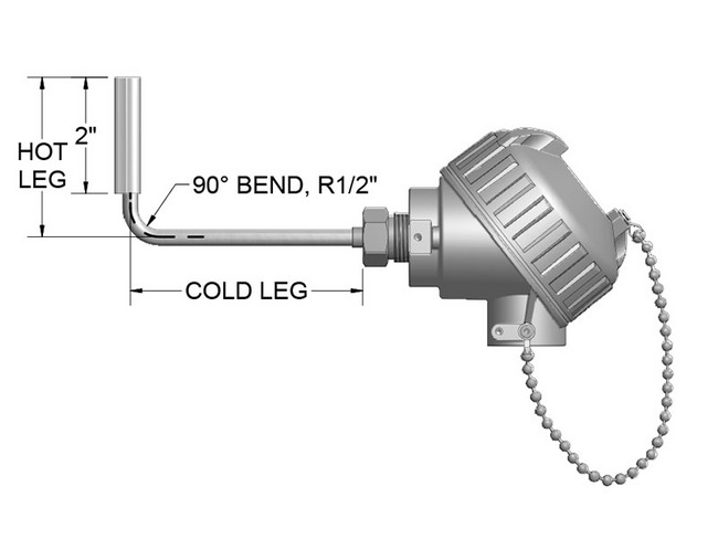
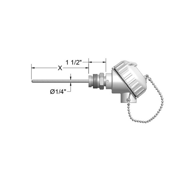
RTD Resistance Temperature Detector. RT DOOR CB BLOWER. T-620H Pump Connection Diagram.
BRX 10 PLC MPU - Layout. 250 V reference output with 1 accuracy. BRX 10E PLC MPU - Layout.
Backup Lamps Trailer Wiring. Micro EHV PLC Thermocouple Modules - Layout. The SEPTA subwaysurface trolley lines are a collection of five SEPTA trolley lines that operate on street-level tracks in West Philadelphia and Delaware County Pennsylvania and also underneath Market Street in Philadelphias Center CityThe lines Routes 10 11 13 34 and 36 collectively operate on about 396 miles 637 km of route.
Automatic UPS System Wiring Circuit Diagram One Live Wire Ordinary Wiring Automatic UPS Inverter Connections. Bridge transducers FUNCTIONAL BLOCK DIAGRAM Healthcare and wearables Figure 1. Approximately 10 times more accurate.
Micro EHV PLC RTD Modules. IP67 terminal block connector RTD module not included. BRX 18 PLC MPU.
Micro EHV PLC RTD Modules - Layout. Powertrain Control Module Fuel Pump. Instrument Panel Fuse Block.
Function Block Diagram Structured Text Sequential Function Chart Ladder Logic Diagram and Instruction List. Fuses Usage RR Wiper Rear Window Wiper Switch SEO ACCY Special Equipment Option Accessory WS WPR Windshield Wipers TBC ACCY Truck Body Controller Accessory IGN 3. Fuse box diagram.
BODY 12 WAY BROWN Fuse Block Left IP C3 Body Harness CB LT DOORS 25A Window Switch LR Driver Door Module DDM 2004 Chevrolet Silverado Relay Block. 0 8 2 X1 0 8 2 46 X10 P. STUD 1 40A Trailer Wiring Automatic Level Control ALC Compressor Relay MBEC 1 50A SEAT CB.
2004 Instrument panel fuse block The fuse block access door is on the drivers side edge of the instrument panel. The fuse block access door is on the drivers side edge of the instrument panel. MPLAB Harmony is a modular framework that provides interoperable firmware libraries for application development on 32-bit microcontrollers MCUs and microprocessors MPUs.
The 339 contains a full range of self contained protection and control elements as detailed in the Functional Block Diagram and Features table. In order to measure the process variable ie temperature a sensor is used let us say an RTD. ArmorBlock and Armor WeldBlock IO Block Connections The following diagrams are examples of the network IO power connections and block dimensions that are available on ArmorBlock and Armor WeldBlock IO blocks.
Thermocouple Types Construction Working and Applications. BRX 10E PLC MPU. Compatible with NTC or RTD thermal sensors.
New report faults DIA for heavy-handed oversight that contributed to breakdown of Great Hall Project Lessons learned review also assigns blame to contractors for conflicts delays and overruns. T-1 Pump Connection Diagram. Real Time Damping RTD RR PRK Fuse 29.
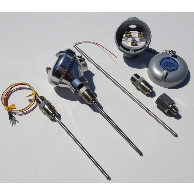
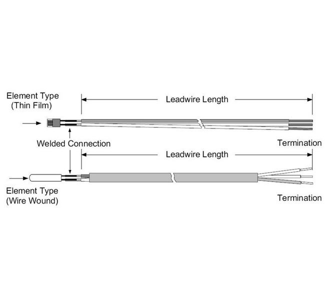
Identifying and legend fuse box Chevrolet Silverado 1999-2007. SEPTAs Route 15 the Girard. 4126 RTD 3-wire Single Std temp RTD Pt385Class B 012 accuracy 100 ohm 4 x 316 diameter 316SS probe.
Makes u lose more mana 0 Febuary13th. For specific connections available on a particular block see the installation instructions for that block. Assume that the process variable is temperature in centigrade.
From the sensitivity point of view while both RTDs and Thermocouples respond quickly to temperature changes at similar costs thermocouples are often faster. GaugeCalHP Pump Connection Diagram. Block Diagram and Features table.

How To Draw A Schematic Diagram Diagram Safety Fail Education
2

Regional Transportation District Wikiwand
Resistance Temperature Detectors Rtd Manufacturers And Suppliers In The Usa
Temperature Sensors Manufacturers And Suppliers In The Usa

Module 2 Flashcards Quizlet
2
Resistance Temperature Detectors Rtd Manufacturers And Suppliers In The Usa

Power Cable Customizer Wooden Camera
Xw Eda Universal Process And Temperature Wireless Transmitter

Water Cooled Engine Diagram Free Electrical Diagram Water Cooler Electrical Wiring Diagram
2

Schematic Map I Made Of Rtd Rail Transit In The Denver Metro R Denver

Field Transmitter Calibration Error Comandos Eletricos Sistema De Controle Sensor De Pressao
Gaimc 4 20ma Smart Rtd Pt100 Thermocouple Head Temperature Transmitter Price Buy Thermocouple Head Temperature Transmitter Pt100 Head Temperature Transmitter Smart Head Temperature Transmitter Product On Alibaba Com
Temperature Sensors Manufacturers And Suppliers In The Usa
Schematic Map I Made Of Rtd Rail Transit In The Denver Metro R Denver